Phase Verification
Bridges
Model 5002
DESCRIPTION
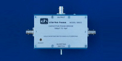
The Model 5002 Phase Verification Bridge set comprises passive devices that are used in
conjunction with Model 5500-2 Phase Standard and an output null
indicator such as a true rms voltmeter, an oscilloscope or a wave analyzer to verify that
the Phase Standard is continuing to operate within its specified phase accuracy limits.
Each bridge has two input terminals for the two output terminals of the Phase Standard and
an output terminal to which the null indicator is connected An impedance (a resistor
or a capacitor) is connected between each input terminal and the output terminal.
The set comprises four bridges:
(1) 5002A. A one-to-one resistive bridge.
Nominal loading of 50kW at its two inputs
at balance. Usable from 1Hz to 50kHz. Inherent phase error less than ±1m° to 1kHz
and ±2m° to 50kHz.
(2) 5002B. A one-to-one capacitive bridge.
Nominal loading of 900pF at its two inputs at balance. Usable from lkHz to 200kHz.
Inherent phase error less that ±2m° from 1kHz to 50kHz and less than ±8m° to
200kHz. (May be used below lkHz if special precautions are observed)
(3) 5002C. A ten-to-one capacitive bridge.
Nominal loading of 900pF and 90pF at its two inputs at balance. Usable from lkHz to
200kHz. Inherent phase difference from the Standard C Bridge between 5kHz and 50kHz is
less than ±2m° and less than ±8m° to 200kHz.
(4) 5002D. A hundred-to-one capacitive bridge. (Picture above)
Nominal loading of 1000pF and l0pF at its two inputs at balance. Usable from lkHz to
200kHz. Inherent phase difference from the Standard D Bridge between 5kHz and 50kHz is
less than ±2m° and less than ±8m° to 200kHz.
In addition to the bridges, each set contains three interconnecting
coaxial cables, an Instruction Manual and a set of data comparing the particular Bridge
Set to the Standard Bridge set developed by Clarke-Hess.
OPERATION
A four arm bridge has a single generator, and at least two arms are adjusted to produce
the minimum output. With the Phase Standard, two outputs exist with an adjustable phase
shift between them. This means that two arms are sufficient for the bridge. The bridge can
be balanced by adjusting the relative amplitude of the two generators and the phase angle
between them. If the two impedance arms of the bridge have identical phase
angles, the bridge will balance when the phase angle between the two bridge inputs is
exactly 180°, and each input amplitude divided by the magnitude of the
impedance connected to its input has the same value. All of the bridges are designed and
constructed so that the two impedances have identical phase angles over a broad range of
frequencies.
Since, in general, the two adjustments are independent, the amplitude
balance can be made and then the phase balance. In practice, the amplitude
gradations available from the Phase Standard, even though they are often as small as 1mV,
are not sufficient to allow an accurate amplitude balance. To solve this problem, each
bridge includes an AMPLITUDE vernier which permits the adjustment of the amplitude between
the amplitude settings of the Phase Standard. Since the trimmer is of the same impedance
type as the main arm of the bridge, it adjusts the amplitude without causing phase shifts.
The difference between the phase indication on the Phase Standard at balance and
180° is the phase error in the Standard plus any small error in the
bridges. Usually an offset of 180° is entered into the Phase
Standard and the phase indication at balance becomes the phase error.
Increased Measurement Resolution
When an rms voltmeter is used as a null detector, its internal noise
(and sometimes the minimum amplitude before the display is forced to zero) prevent an
accurate determination of the null position. This problem can be overcome by
setting the offset at 180°, balancing the bridge as well as possible,
entering a large negative angle into the Phase Standard and recording the rms output
voltage, entering the same magnitude angle, only positive, into the Phase Standard and
recording the rms output voltage and then utilizing the following formula.
Phase error = Ø [Vneg
- Vpos] / [Vneg + Vpos]
where Ø is the magnitude of the large angle
in degrees, Vneg is the rms output for the negative angular
deviation and Vpos is the rms output for the positive
angular deviation. The Phase error is in degrees and has a resolution of a fraction
of a millidegree.
CALIBRATION
When the magnitude of the impedances in the two arms of the bridge are equal, the
calibration of the bridge is very straight forward and can be done at the same time
the error in the Phase Standard is being determined. This is accomplished by first
determining the phase error as described above and then, without adjusting anything,
interchanging the two input cables to the bridge and determining the phase error a second
time. As can be easily shown, the sum of the two phase errors divided
by 2 is the error in the Phase Standard and the difference of the two phase errors divided
by 2 is the error in the bridge. If there is no bridge error, both phase
errors are the same and equal to the Phase Standard error. If there is no Phase
Standard error, the phase errors are equal and opposite in sign and track the bridge as
its position is reversed.
When the magnitude of the impedances of the two arms of the bridge are
not equal, the bridge is calibrated by the comparison method. In this case, the
bridge to be calibrated and a Standard Bridge having the same ratio of the impedance
magnitude of both arms as the bridge under test, are connected in parallel to the same
Phase Standard. That is, a "tee" is placed on each output of the Phase
Standard and the two equal length cables connected to each "tee" are connected
to the corresponding inputs of each bridge. Each bridge has its own rms voltmeter
connected to its output Both bridges are nulled and the Phase Standard is deviated
to obtain the Phase Error of both bridges simultaneously. Since the Phase Standard
component of both errors is the same, the difference of the two errors is the
error of the bridge under test relative to the Standard Bridge.
STANDARD BRIDGES
A Standard Bridge is a bridge that is known to have the same phase angle
for the impedances in both of its arms. When such a bridge is used with the Phase
Standard, the entire phase error away from 180° is due to the Phase
Standard. When such a bridge is constructed, it can be used as a standard to
calibrate other bridges as discussed in the preceding section.
The two ways of obtaining two impedances with the same phase angles at
a large number of frequencies is to match them or to select impedances with known
properties. Clarke-Hess uses the former approach while the U.S. Air Force uses the
latter.
The Air Force approach is to use variable air dielectric capacitors
with dissipation factors less than 0.00001 in both arms of the bridge. (A dissipation
factor of 0.00001 corresponds to an angle of 0.00057°.) Such
capacitors were supplied by General Radio, Inc. Model 722D is a low loss air
dielectric capacitor variable from 110pF to 1100pF. With one of these capacitors for
each bridge arm, any desired ratio of impedance can be set up. The Air Force has
used this bridge for calibrating over 200 Clarke-Hess Phase Standards which they have
purchased over a 16 year period.
The Clarke-Hess approach is to obtain a large number of low
dissipation, high quality multi-layer ceramic capacitors and match them for phase angle at
a number of frequencies between 100Hz and 200kHz. Two 900pF capacitors matched in
such a fashion are used in the arms of the Model 5002B bridge. Eleven 900pF phase
angle matched capacitors ar e used in the arms of the Model 5002C bridge. Ten are
placed in series to form the 90pF arm while a single one is used for the 900pF arm.
Twenty 100pF phase angle matched capacitors are used in the arms of the Model 5002D
bridge. Ten are placed in series to form the 10pF arm while ten are placed in
parallel to form the 1000pF arm.
The capacitors are matched in a test jig which resembles a 1:1
capacitor bridge. A reference capacitor is placed in one arm and the capacitor under
test is placed in the other arm. The Phase error is recorded at all frequencies of
interest. Keeping the same reference capacitor, the procedure is repeated for a
second capacitor, and so on. Capacitors with the same set of phase errors for the
differing frequencies are matched. The fact that the loss and the dissipation factor
of these capacitors is low, keeps the Phase error terms low and thus makes the matching
reasonably straight forward.
Confidence in this procedure has grown over the years as the number of
bridges produced, using capacitors from different manufacturers, all resulted in bridges
which were essentially identical to the in-house reference bridge set, S/N 71. In
particular, typical agreement was within 1m° from 100Hz to 50kHz and
within 4m° to 200kHz. Bridges constructed in this fashion do
indeed provided an intrinsic standard for measuring errors in phase angle.
Resistance Bridges
Capacitor Bridges become very high impedances at low frequencies (below 100Hz)
and are subject to phase errors because of parallel resistance loss. Consequently,
for low frequency phase measurements, bridges with resistive arms are superior.
Because of unequal stray capacitance across the two resistors, the phase error in such a
bridge increases with increasing frequency. (Low loss stray capacitance has no effect on
the angle of a capacitor bridge). To make such a bridge essentially perfect, in the
1:1 case, a variable capacitor, in the form of a wire bent over the resistor with the
lower amount of stray capacitance, is adjusted until the bridge has no error at 50kHz as
determined by the bridge reversal method. With this adjustment, similar bridge
reversal measurements at other frequencies always indicate that the bridge produces very
little phase error. Very little error is also indicated when the 1:1 resistive
bridge, Model 5002A is compared with the Model 5002B capacitive bridge.
NO STANDARD PHASE ANGLE
Unlike the standard meter and the standard Volt, there is no standard
Phase Angle at any of the national laboratories. Because of this, one has to rely on
the properly constructed bridge set as an intrinsic standard to verify the proper
performance of phase generating devices at an angle of 180°.
Because of the long history at Clarke-Hess of producing hundreds of Phase Standards and
Phase Bridges, comparing each and every one of them with previously manufactured Phase
Standards and Phase Bridges and finding the results with a very tight statistical error
bound, Clarke-Hess has every confidence that any piece of phase equipment they
produce is well within any published tolerances. |