- Color Graphical Touch Sens. Display
- 7 Volt Compliance
- 100 Amperes to 100 kHz Model 8200
- 100 Amperes to 10kHz Model 8210
- 200 mA to 100A in six ranges
- 100% over range capability
- 40ppm short term stability
- 0.04% dc and 0.10% ac accuracy
- Accuracy independent of load
- Distortion below -60dB
- Complete Front Panel Calibration
- IEEE-488.2/USB Interface
- Stable with inductive loads
- High output impedance
- Low Acoustic Noise
Transconductance Amplifier
Model 8200/8210
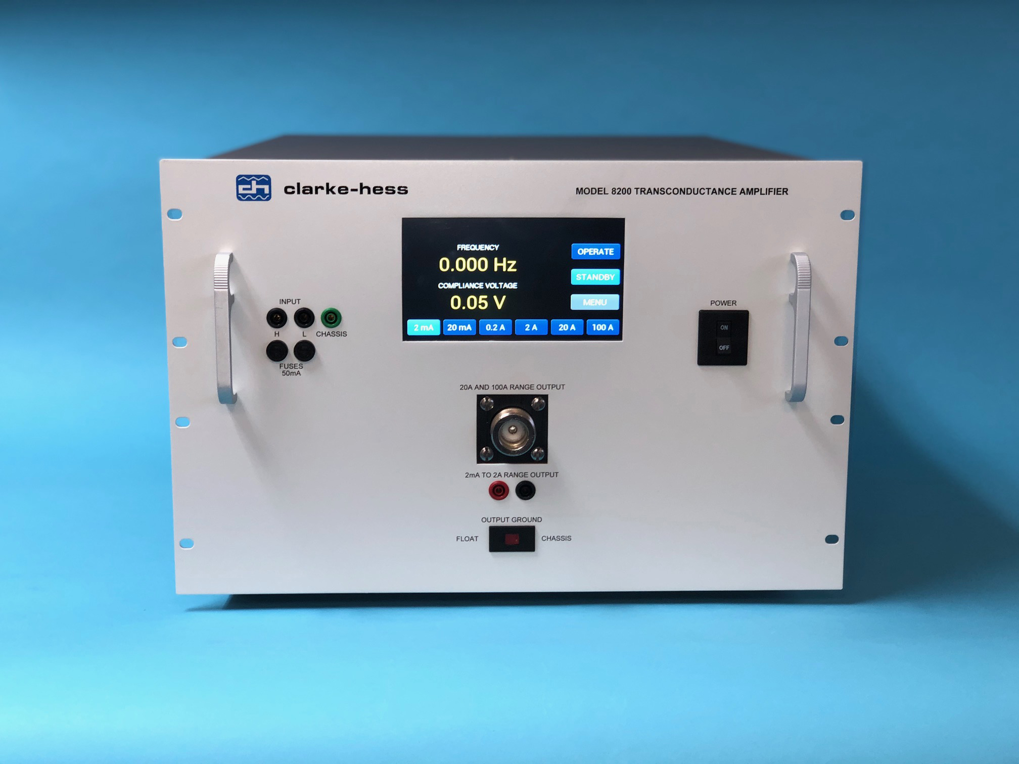
DESCRIPTION
The Model 8200/8210 Transconductance Amplifiers are precision, high stability, high accuracy instruments which produce an output current which is directly proportional to the input voltage over the frequency range from dc to 10 kHz (Model 8210) or to 100kHz (Model 8200). Six overlapping ranges, with full scale values of 2mA, 20mA, 0.2A, 2A, 20A and 100A, provide low distortion output currents from 200uA to 100A. With the exception of the 100A range, for which a 1 V rms input produces the 100 Arms output current, the transconductance of the other ranges is set such that a 2Vrms input produces the full scale output current. With the exception of the 100A range, all of the other ranges may be operated to twice their full scale value without any deterioration in performance.